All posts by admin

Getting Pre-Plate Pitch Diameter Right: Calculating for Thread Growth During Plating

When manufacturing threaded components that will be plated, it’s easy to overlook one critical factor: the coating adds thickness. That added material changes thread fit, function, and ultimately compliance with drawing requirements. To prevent costly rejects or rework, manufacturers calculate the pre-plate pitch diameter — the thread size before plating — to ensure that once the coating is applied, the finished thread meets its target class of fit.

Understanding how to properly calculate and verify pre-plate pitch diameters is essential for anyone in the thread manufacturing or calibration business. Whether you’re a machinist, quality engineer, or metrology lab technician, this process combines geometric principles, coating data, and gauging know-how.


Why Pre-Plate Pitch Diameter Matters

Plating and coating processes, such as zinc, nickel, chrome, or cadmium, apply a uniform (or near-uniform) layer of material on all surfaces of a threaded part. While this layer improves corrosion resistance and appearance, it also alters the geometry of the threads:

  • For external threads, plating increases the pitch diameter and major diameter.
  • For internal threads, plating reduces the pitch diameter and minor diameter.

If a manufacturer machines threads to the nominal (finished) size and then plates them, the result will likely be oversized external threads or undersized internal threads. Both conditions can cause interference fits or assembly issues.


The Formula: How to Calculate Pre-Plate Pitch Diameter

To ensure that the finished (post-plate) thread falls within the required limits, you must calculate and machine the pre-plate thread undersize or oversize to compensate for the coating buildup.

1. Establish Known Values

You’ll need:

  • Specified plating thickness (T) – measured per surface, usually in microinches (µin) or micrometers (µm).
  • Nominal pitch diameter (PDn) – the target after plating.
  • Thread type – external or internal.
  • Thread pitch (P) – required for reference when inspecting with wires or measuring equipment.

2. Apply the Correct Compensation Formula

Because plating occurs on all thread flanks, the thickness affects both sides of the pitch diameter.

For external threads: PDpre=PDfinished−(4×T)PD_{pre} = PD_{finished} – (4 \times T)PDpre​=PDfinished​−(4×T)

For internal threads: PDpre=PDfinished+(4×T)PD_{pre} = PD_{finished} + (4 \times T)PDpre​=PDfinished​+(4×T)

Why the multiplier of 4?
Each flank of a 60° thread receives a coating thickness of T, but due to the flank angle, the effect on the pitch diameter is 2 × T × cos(30°) per side, or approximately 1.732 × T. For simplicity and conservatism, the industry uses 4 × T as a rule of thumb to ensure adequate compensation. For fine control, use the exact geometry-based relationship: ΔPD=2×T×1sin⁡(30°)=4×T\Delta PD = 2 \times T \times \frac{1}{\sin(30°)} = 4 \times TΔPD=2×T×sin(30°)1​=4×T


Example Calculation

Let’s say we’re producing a ½-20 UNF-2A external thread that will receive 0.0002 in. of zinc plating per surface.

  • Target finished PD (from ASME B1.1 tables): 0.4675 in.
  • Plating thickness (T): 0.0002 in.

PDpre=0.4675−(4×0.0002)=0.4667 in.PD_{pre} = 0.4675 – (4 \times 0.0002) = 0.4667 \text{ in.}PDpre​=0.4675−(4×0.0002)=0.4667 in.

Therefore, the thread should be cut to a pre-plate pitch diameter of 0.4667 in. to achieve a finished dimension of 0.4675 in. after plating.


Inspection and Verification Methods

Once you’ve calculated the pre-plate pitch diameter, verification through measurement is critical. There are two primary methods used in industry:

1. Three-Wire Method

The three-wire method remains the most accurate way to determine pitch diameter on precision threads. It uses calibrated wires of known diameter placed in the thread flanks, and a micrometer measurement gives a “measurement over wires” (MOW) value. From this, pitch diameter is calculated using formulas from ASME B1.2 or ISO 1502.

For pre-plate verification:

  • Use traceable wires and ISO/IEC 17025–calibrated micrometers.
  • Record results before and after plating to confirm actual coating buildup.

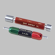
2. Fixed Limit Gauging

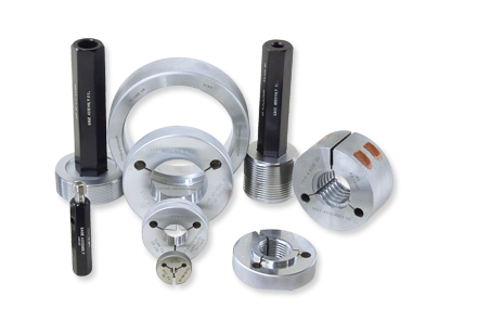
Many manufacturers prefer GO/NO-GO thread ring or plug gauges for production checks. Pre-plate gauging often uses special pre-plate master gauges manufactured with the adjusted (pre-plate) dimensions. This ensures production threads are machined correctly before plating.

Walden Gage and other accredited gauge makers can produce pre-plate master setting plugs or rings to a specified target PD, ensuring the gauging aligns perfectly with plating requirements.


Accounting for Real-World Variability

In practice, plating thickness is rarely perfectly uniform. Variations occur due to part geometry, process control, and current distribution. To manage this:

  • Consult your plating supplier for actual thickness control data.
  • Use statistical sampling of coated parts to refine your compensation factor.
  • Specify tolerance bands in drawings (e.g., “plating thickness 0.0002 ± 0.00005 in.”).
  • Verify post-plate thread fit with GO/NO-GO gauges traceable to ISO/IEC 17025 standards.

Even small deviations — on the order of 0.0001 in. — can shift a thread from Class 2A to a borderline 3A fit, affecting interchangeability.


Reference Standards and Resources

  • ASME B1.1-2019: Unified Inch Screw Threads (UN and UNR Thread Form)
  • ASME B1.2-1983 (R2008): Gages and Gaging for Unified Inch Screw Threads
  • ISO 965-1:2013: General Purpose Metric Screw Threads – Tolerances
  • NIST Technical Note 1297: Guidelines for Evaluating and Expressing Uncertainty
  • SAE AMS 2469 / ASTM B633: Specifications for Electroplated Coatings
  • ILAC P14:09/2020 – Traceability of Measurement Results

Conclusion

Getting pre-plate pitch diameters right isn’t just a matter of arithmetic — it’s a quality-critical control that ensures functional thread fit after coating. By applying proper compensation formulas, verifying with accredited gauging, and maintaining control over plating variability, manufacturers can achieve consistent, compliant threads and reduce costly rework.

Whether you rely on three-wire measurement or fixed limit gauging, the key is consistency, traceability, and adherence to the latest ASME and ISO standards. Accurate pre-plate pitch diameter calculation is one more step in building confidence that what’s on the print is what’s in production — every time.

Thread Form Integrity: How Go/No-Go Gages Reveal More Than Just Pitch Diameter Errors

In thread inspection, the Go/No-Go gage has long been the trusted final word on whether a threaded component meets specification. But while many quality teams think of these fixed limit gages as simple “fit” indicators, their role is far more nuanced. Each pass or fail outcome is the result of a precise geometric relationship between the gage’s thread form and the part’s actual thread geometry.

Understanding how Go/No-Go gages interact with thread form integrity—not just pitch diameter—is critical for anyone responsible for maintaining quality in precision manufacturing. Subtle deviations in flank angle, lead, or profile truncation can produce misleading results, where a thread may technically “fit” but still fall short of its intended function.


Beyond Pitch Diameter: The True Nature of Thread Fit

Thread inspection often centers on the pitch diameter, the imaginary cylinder where the width of the thread ridge equals the width of the groove. While this is a key functional parameter, the Go/No-Go gage evaluates more than just size.

Because the gage’s thread form is manufactured to the same geometry as the nominal design, it simultaneously checks multiple elements at once:

  • Flank angle — typically 60° for Unified and Metric threads
  • Lead (or pitch) — the linear advance per revolution
  • Crest and root truncation — ensuring proper clearance and engagement depth
  • Thread roundness and straightness

If any of these elements deviate—even within small limits—the fit of the Go plug or No-Go ring gage will change. The gage may falsely indicate a pass if flank angle errors compensate for undersize pitch diameter, or vice versa. This interdependence is what makes gage calibration and proper use essential to accurate thread verification.


How Go/No-Go Gages Interact with Thread Form

Each Go/No-Go inspection effectively performs a form comparison between two mating geometries. When a Go gage is inserted into a threaded component:

  • A Go plug gage (for internal threads) must freely enter without excessive force.
  • A No-Go plug gage must not enter more than two full turns.

The opposite applies for external threads inspected with ring gages.

However, when a thread form deviates—for example, if the flank angle narrows slightly—the contact point between the gage and the part shifts. This changes the effective pitch diameter the gage perceives. A narrow flank angle can make a part appear “tight,” while a wide angle may cause premature acceptance of an undersized thread.

Similarly, lead variation or drunken threads (nonuniform pitch along the axis) can create localized tight spots. In such cases, the Go gage may enter smoothly at the start but bind deeper into engagement. While that might look like a simple dimensional issue, it actually signals a geometric inconsistency—a condition Go/No-Go gages are uniquely sensitive to, even when variable measurements miss it.


Fixed Limit Gaging and ISO 17025 Traceability

Under ISO/IEC 17025, calibration laboratories must demonstrate traceability of all measurement results to the International System of Units (SI). For Go/No-Go thread gages, this traceability chain connects back to national standards such as NIST Master Thread Gages in the United States or UKAS-accredited standards in the UK.

A properly accredited calibration ensures:

  • The gage’s pitch diameter is measured using certified master wires or rings.
  • The thread form (flank angle, lead, and roundness) meets Class X or better geometry tolerances per ASME B1.2 or ISO 1502.
  • The calibration process includes uncertainty analysis that considers temperature, alignment, and measurement method.

When a manufacturer uses ISO 17025–calibrated gages, each pass/fail result is traceable to an unbroken chain of standards. That means when a Go gage fits—or fails—it reflects not only dimensional accuracy but also internationally recognized thread form integrity.

(See: NIST Master Thread Plug and Ring Gages, ISO 1502:1996 – ISO Metric Screw Threads — Gauges and Gauging)


Common Causes of Misleading Go/No-Go Results

Even with well-calibrated tools, the interaction between gage and thread can be distorted by real-world factors:

  1. Gage wear and dirt
    Worn flanks or debris in the gage thread can mimic a “tight” fit, suggesting an undersized part. Regular cleaning and inspection are essential.
  2. Over-torquing during use
    Applying excessive force to a No-Go gage can damage the thread form and produce false rejects. Gages are meant to feel, not force.
  3. Temperature variation
    Even a few degrees of difference between the gage and part can cause thermal expansion that alters fit perception.
  4. Mismatched thread classes
    Using a Class 2A ring on a Class 3B internal thread, for example, invalidates the inspection. Always verify both gage and workpiece class.
  5. Uncalibrated thread wires or master rings
    A gage verified with untraceable masters undermines the entire measurement chain, violating ISO 17025 traceability principles.

Thread Form and Functional Fit: Why It Matters

A part can have a perfect pitch diameter and still fail in service if its thread form is off. Poor flank engagement reduces load-bearing area and leads to early stripping or fatigue failure. Conversely, overly truncated crests can cause excessive play, vibration, and leakage in pressure fittings.

In safety-critical industries like aerospace or medical devices, these small errors can have serious consequences. That’s why many quality engineers now supplement Go/No-Go gaging with form measurement techniques—such as optical thread scanners or coordinate measuring machines (CMMs)—to visualize the actual thread geometry.

Still, Go/No-Go gages remain the most practical and immediate method for verifying both size and form interaction on the shop floor. When properly calibrated and handled, they provide a remarkably sensitive indicator of real-world fit.


Best Practices for Gage Calibration and Use

To get the most reliable results from Go/No-Go gages:

  • Schedule calibration intervals based on usage frequency and material hardness, not just time.
  • Store gages in a controlled environment to minimize thermal cycling and corrosion.
  • Verify thread form geometry as part of calibration—not only pitch diameter.
  • Train operators to interpret tactile feedback correctly. A “feel” gage requires skilled handling.

When these practices are combined with ISO 17025–accredited calibration, manufacturers can confidently rely on their Go/No-Go gages to detect even subtle thread form deviations before they cause costly rework or field failures.


Conclusion

Go/No-Go gages do much more than confirm if a thread “fits.” They are a mechanical expression of the complete thread geometry—flank, lead, truncation, and roundness—brought into physical contact with a precisely calibrated standard.

By understanding how these gages interact with thread form, and by maintaining traceable calibration under ISO/IEC 17025, manufacturers can ensure that every accepted thread is not only dimensionally correct but functionally sound. In an era of increasing precision and accountability, thread form integrity is the real measure of quality—and the humble Go/No-Go gage remains one of its most effective guardians.

“Getting Thread Gauging Right: Best Practices for Go/No-Go Thread Plug & Ring Gages”

In any manufacturing process involving threaded components—bolts, nuts, threaded holes, tappet threads—the inspection of those threads is a critical control point. Using thread gauges correctly ensures you are making the right “attribute” decision: the part either meets the specification or it doesn’t. But simply handing a thread plug or ring gauge to an operator and expecting perfect results is risky. Today, we’ll walk through a systematic approach to proper usage of thread gauges, covering selection, setup, inspection technique, maintenance and calibration links to quality systems.

1. Select the correct gauge for the job

First and foremost: ensure you are using the right type of gauge for your threaded feature. There are two complementary styles:

Thread plug gauges (Go/No Go) for internal threads (nuts, tapped holes)

Thread ring gauges (Go/No Go) for external threads (bolts, studs)
Quality Magazine:
https://www.qualitymag.com/articles/94425-thread-basics-go-no-go-acceptance

Here are key selection pitfalls:

Matching the specification on the drawing exactly: thread size, series, class of fit (e.g., 2A/2B or 3A/3B) must correlate with the gauge you use. Using a 3B-class ring gauge on a 2A external thread is incorrect and can lead to bad parts passing or good parts rejected.
CrossCo:
https://www.crossco.com/resources/articles/mistakes-to-avoid-thread-gages

Understanding the difference between setting gages and working/wear check gages. Setting plugs or ring masters are calibrated to master standards and are not designed for production checking—they should not be used in place of a working Go or No-Go member.
CrossCo:
https://www.crossco.com/resources/articles/mistakes-to-avoid-thread-gages

Ensuring the gage reaches the required depth of thread in the part. For example, No-Go members must engage the thread for the correct number of turns (often 2½–3 turns) to validate size across length; if your part is shorter, you may need a special gage.
Quality Magazine:
https://www.qualitymag.com/articles/94425-thread-basics-go-no-go-acceptance

Matching materials and wear characteristics: if you’re gauging a hard material part, a standard tool-steel gage may wear prematurely and lead to mistaken acceptance. As one article advises: consider chrome‐plated or carbide gages for high usage/hard parts.
CrossCo:
https://www.crossco.com/resources/articles/mistakes-to-avoid-thread-gages/

2. Prepare the environment, instrument and part

Even the best gauge can give erroneous results if environmental, usage or handling conditions are sub-optimal. Key steps include:

Confirm that both the part and the gauge are at the calibration reference temperature (commonly 20 °C / 68 °F). Thermal expansion between the part and the gage can cause false rejects or false accepts.
https://elsmar.com/elsmarqualityforum/threads/controlled-environment-environmental-requirements-for-calibrations.16424

Clean the gage and the part: remove chips, burrs, lubricant residue, corrosion or debris that could interfere with thread engagement. A dirty or damaged thread surface can mask a size error.

Apply a thin film of appropriate lubricant on the gage to reduce friction and avoid galling, particularly for long threads or high-volume usage.

Inspect the gage for signs of wear, damage, chips or nicks before use. A gage with worn threads may incorrectly accept out-of-tolerance parts.

Make sure the part is properly fixtured/stabilized and aligns with the axis of the gauge insertion to avoid skewing the engagement or seating of the Go/No-Go feature.

3. Perform the inspection correctly

When you’re ready to inspect, follow a consistent method and record results (as applicable) for traceability.

Go member (should fit):

Insert or run the Go end of the gage with controlled hand force (avoid excessive torque or mechanical drive). The Go should engage fully to the depth required (or until the stop feature). If it does not fully enter, the thread is too small or not deep enough.
Quality Magazine:
https://www.qualitymag.com/articles/94425-thread-basics-go-no-go-acceptance

For internal threads, insert the Go plug and wind carefully—avoid forcing. For external threads, screw on the Go ring until it seats.
No-Go member (should not fit):

After the Go passes, attempt the No-Go. It must not fully engage beyond the allowed number of turns (commonly 2½–3 complete turns) or thread depth. If it does, the feature is too large or oversize.
Quality Magazine:
https://www.qualitymag.com/articles/94425-thread-basics-go-no-go-acceptance

Record the result: pass or fail. Ensure the decision point is clear: if Go passes and No-Go fails → part acceptable. Any other result → reject.

4. Review and interpret results

It’s important to treat this as an attribute gage decision—Go/No-Go is not providing you a dimension; it’s giving a “yes/no” outcome.
Walden Gage Calibration Services:
https://www.foxvalleymetrology.com/blog/thread-inspection-101-part-i-thread-gage-basics

Some additional considerations:

If many rejections occur, check the gauge (for wear/damage), check the process (machining, tapping, plating shrinkage) and confirm correct specification.

Periodically verify gage performance against a master or reference standard—even though the operator performs Go/No-Go, the gage itself must be verified in the calibration program.

Keep in mind that uncertainty of the measurement chain (including gage wear, environmental drift, operator variation) must be considered, especially when tolerances are tight. In some cases, measurement uncertainty may be a significant fraction of tolerance.
Quality Magazine:
https://www.qualitymag.com/articles/95656-dealing-with-measurement-uncertainty?

Record inspection data, traceability log of gages, calibration status, and any deviations—for internal audit and for linking to your accredited calibration system (e.g., ISO/IEC 17025).

5. Maintenance, calibration and lifecycle of thread gauges

Proper care and maintenance extend the life of your gauges and support your quality system. Consider the following:

Regular cleaning and protective coating (oil, wax film) after use, especially in humid or corrosive environments.

Store thread plug and ring gauges in protective cases or racks to avoid impact, deformation or contamination.

Inspect gages periodically: look for wear on Go ends (which typically wear faster) and on No-Go seating ends. Replace or re-calibrate when wear is evident.

Schedule calibrations at intervals based on usage, tolerance criticality, environment and history of wear. Some references indicate that for gages in heavy use or hard material parts, calibration and inspection frequency should increase.
Cutwel:
https://www.cutwel.co.uk/blog/thread-gauge-calibration?

Choose a calibration laboratory that is ISO/IEC 17025-accredited and has traceability to national standards. This ensures that your calibration results are accepted internally and externally, and you maintain the measurement traceability chain.

A Guide to ISO 17025 Calibration Standards and Compliance

Document calibration certificates, gage identity, calibration interval, results including measurement uncertainty (which may be relatively large for thread gages).
Quality Magazine:
https://www.qualitymag.com/articles/95656-dealing-with-measurement-uncertainty?utm_source=chatgpt.com

6. Integrating with your quality system

From a management/quality‐systems perspective, incorporating thread gauge usage into your inspection procedure supports consistency, traceability and audit readiness:

Define a standard operating procedure (SOP) for thread gauging (selection, handling, inspection method, decision criteria, record keeping).

Train operators on correct gage usage—avoid common mistakes like forcing the gage, using the wrong class of fit, or using setting gages in production.
CrossCo

Maintain a gage log: include gage ID, size/class, calibration date, next due date, usage count (if tracked), wear history.

When changes occur (new part design, plating change, thread form change), review your gage inventory and ensure you still use the correct gauge or if a new/custom gage is required.
https://www.crossco.com/resources/articles/mistakes-to-avoid-thread-gages/

Monitor inspection results: a sudden increase in No-Go failures may indicate gage wear, process drift or incorrect gage use. Use this as a trigger for root-cause action.

Link the gage maintenance and calibration schedule to your quality system documentation (for example, referencing that your calibration provider is ISO/IEC 17025-accredited and maintains traceability). This links back to your audit readiness and continuity of measurement assurance.

Conclusion

Correct use of thread gauges is more than just handing them to an operator: it involves selecting the right gauge, setting up the environment and part, following a consistent inspection method, ensuring gage integrity and calibration, and embedding the process in your quality system. For manufacturers of threaded parts, these steps reduce risk, support measurement confidence, and improve production consistency. When your thread gages are well-managed and your operators well-trained, the Go/No-Go decision becomes a strong pillar of your inspection strategy rather than a weak link.

SPLINE GAGING NOW AVAILABLE!

Walden Gage is always striving to provide our clients with access to the highest quality in all lines of fixed limit gaging. Spline Gaging is no exception. As far as fixed limit gages go, spline gages can be some of the most complex and difficult to design and build. After extensive research and investigation into the methods of manufacture and measurement Walden Gage is pleased to offer access to the nation’s best and brightest manufacturers of these comely measuring instruments. Please contact us today to learn more about how we can help you acquire your unique measurement solution!

WALDEN GAGE IS EXPANDING!

As a small business started in Connecticut, relocated to New York and expanded to include locations in New Hampshire Walden Gage has been focused on expanding the business to better serve you, our valued client. In recent months we have expanded our list of available resources to include familiar names such as Gage Assembly, Hemco Gages, Vermont Gage, PMC Lonestar and many more. Contact us today to learn more about out long list of available resources and new locations that may be coming to your area soon!

NETWORKING VIA SOCIAL MEDIA!

At Walden Gage we have grown our business the old fashion way. Through superior customer service and extensive product knowledge that leads to word of mouth recommendations. In this day and age social media is the ultimate resource for work of mouth recommendations and we are now expanding into this resource in an attempt to provide our clients with an opportunity to share experiences, form relationships and network online with us! Check out our Facebook, Twitter and Linked in pages and get more familiar with Walden Gage and our family of clients and vendors. We look forward to hearing from you!

Quality And Commitment

20 years of experience has provided us with countless relationships on both sides of the quality industry. We work with many of the name brands you see day to day around your facility and we have long standing relationships with many providers you likely have never heard of. Almost all of these relationships have started the same way, and in our opinion, the best way. Through word of mouth recommendation. At Walden Gage we make it a point familiarize ourselves with as many resources as possible because we have come to realize the relationship between a customer and a supplier in many ways mirrors a marriage. With a proper foundation built on a clear understanding of each parties need and wants a partnership between supplier and client can be one that lasts for life.